top of page

KYUNG
YUN
CHOI

CANYVAL-X
NASA GSFC & Astrodynamics and Control Lab, Yonsei Univ.
CANYVAL-X (CubeSat Astronomy by NASA and Yonsei using Virtual Telescope ALignment eXpriement) project has an aim of demonstrating the Vision Alignment System by maintaining flight formation of two separated CubeSats and ultimately prove a possibility of virtual telescope system which is consisted of the optic satellite to focus a light from the sun and the detector satellite. The launch will be held on 2017 January by SPACE-X falcon 9.
From 2012 to 2015, I have been working as a chief engineer on the Structural and Thermal Control System on the cube satellites (CubeSat) development project at the Astrodynamics and Control Lab of Yonsei University, in conjunction with NASA Goddard Space Flight Center (GSFC) Heliophysics Science Division. I designed and manufactured the structures of two CubeSats, which can be controlled to maintain their relative position and distance for formation flight. Also, in order to stabilize their relative distance, I developed a separation control device specialized for CubeSats by making use of a nichrome wire as an actuator. Moreover, I demonstrated an efficient way to load as many solar panels as possible in a limited space by developing the new mechanism of a Double-deployable Solar Panel and analyzing its dynamics and load effects on the CubeSat structure.
Faced with the problem of demonstrating the reliability of the control algorithm prior to its operation in a space environment, I developed a hardware testbed that can simulate the CubeSats motions. My work received recognition when the research paper was published in the 2014 Korean Space Science Society Fall Conference, at which I also gave a presentation.


Award
-
The 2012 Cube Satellite Contest, Finalist, Korea Aerospace Research Institute, Korean Government
Paper
-
G.N. Kim, J.P. Park, K. Y. Choi, J.P Lee, S. Y. Park. ‘CubeSat Structure Design and Lunch Environmental Test for CANYVAL-X Mission’ , The Korean Society for Aeronautical & Space Sciences (KSAS), 2016.
-
J.P. Park, K. Y. Choi, G.N Kim, J.P Lee, J.C Lim, S. Y. Park. et al. ‘Mission Analysis and CubeSat Design for CANYVAL-X Mission’ , AIAA SpaceOps 2016 [pdf]
-
J.C Lim, S.H Lee, K. Y. Choi, G.N Kim, K.W Lee, K.B Lee, J.H Yang, S. Y. Park., ‘CubeSat Solar Panel Designs for CANYVAL-X Mission’, Proceeding of The Korea Space Science Society, Oct. 2015
-
K. Y. Choi, G.N Kim, J.P Lee, S. Y. Park., ‘CubeSat Structure Design and Structural Analysis for CANYVAL-X Mission’ , Proceedings of The Korea Space Science Society, Oct 2015
-
J.P Park, K. Y. Choi, S. Y. Park.‘CubeSat Mission Design for Vision Alignment System Mission’, Proceedings of The Korea Space Science Society, Jun. 2014
Media Appearance
From CAD models to Real model
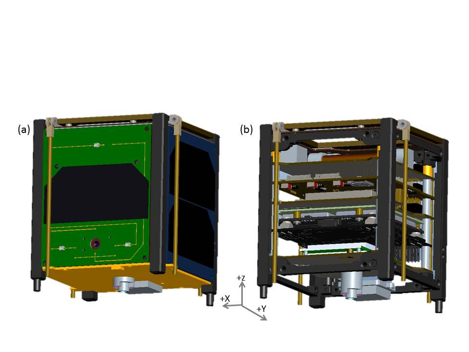
JERRY CAD Model

Tom CAD Model

TOM CAD Model
Solar panels are deployed
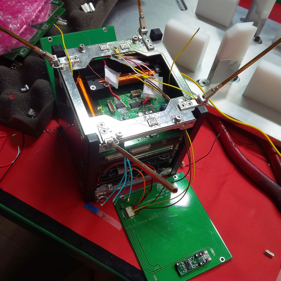
Assembly of Jerry

JERRY-Real Model Integration

TOM-Assembly

TOM-Assembly completed

TOM + JERRY
Connected together by separation control device

The major energy source required for operating subsystems of the CubeSat mission is mainly from the electric power produced by solar panel that placed on the outside of the CubeSat structure. However, the number of solar panel that is allowable for the CubeSat structure’s outer space is limited. In addition to the quantity of the solar panel, the another critical factor for improving electric power production efficiency is depend on its position in the direction of the Sun. In order to increase the amount of electric power production, satisfying the structure constraints as well, I developed a double-deployable solar panel mechanism that is compatible with the CubeSat structural platform of CANYVAL-X mission.
Two 1U-sized solar panels are connected by hinge and two torsional springs composing 1 double-deployable module and 4 modules constitute the completed double-deployable solar panel mechanism. Each module is assembled with hinge that is embedded in each of 4 edges of the square-shaped top hinge panel so that the system form a X-shape. The deployment mechanism enables the double-deployable solar panels to be stowed inward twice and fixed by the devised knot method with Dyneema® string, which simplifies the actuator and requires no extra electric power to make them stayed in stowed state. By using this stowing method, the actuator required for deploying the double-deployable solar panels is unified with the UHF antenna pole deployment system which is GomSpace Interstage.
Moreover, I conducted a dynamic simulation using with MSC ADAMS in order to specify the torsional spring stiffness and the angular velocity variation of 2U CubeSat is estimated as reaction of 2U CubeSat at the moment of the deployment.
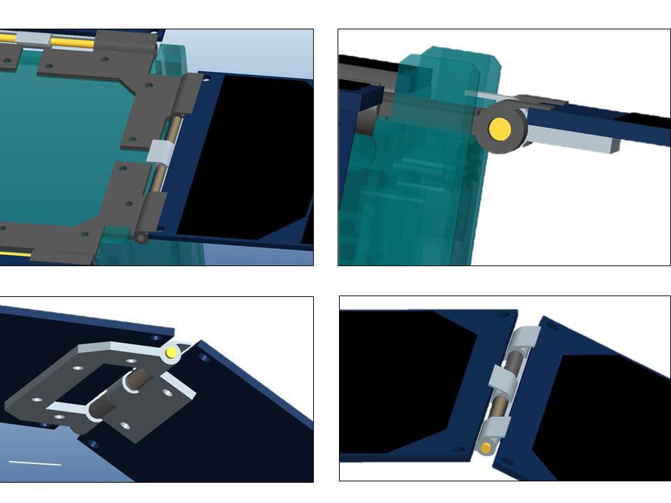
CAD model

Mechanism Components
The principle of this mechanism is using a hinge joint
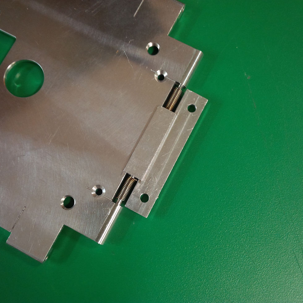
Prototype hinge part
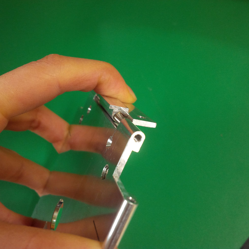
Prototype
It is able to maintain its deployed state angle by joint torsional springs.

Assembled panels
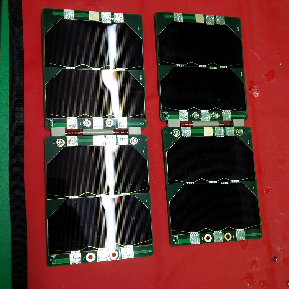
Final version of real solar panels
Development of Double-Deployable Solar Panel Mechanism
Development of CubeSat Separation Mechanism
The primary goal of CANYVAL-X mission is to demonstrate Vision Alignment System in space by developing 1U and 2U CubeSats that cooperate performing a formation flight. In order to make relative position and distance between two CubeSats stable after deployment by P-POD deployer in space, I developed a separation control device that connects two CubeSats, which has very limited space, by making use of a Nichrome wire as an actuator. Two CubeSats is separated by its separation actuating system when the connected two CubeSats unit reaches to the stable state. Through this work, I was able to develop the device in a low-cost and verify its performance.
The separation device consists of two cylinders, two separation poles, and a separation actuating system. Each surface of cylinders contacting each other is forming a stair-shape protrusion that enables them to be coupled, and those protrusions are symmetric when the contact surfaces of each cylinder are facing each other. The stair-shaped protrusion is designed to prevent rotation between 1U and 2U CubeSat on a Z-axis when they interlock so that the separation has the only sliding motion along the Z-axis. All cylinders have a through hole in the middle, which is the passage for the rope that connects 1U and 2U CubeSat structure. The both ends of the connecting rope is tied around the separation poles that are fixed at the each end of 1U and 2U CubeSat structure.
In order to predict how the actuation of the separation device affects the each motion of 1U and 2U CubeSat during separation, dynamics simulation with MSC ADAMS is performed. As a result of the simulation, it is estimated that the relative velocity between 1U and 2U CubeSat after the separation is decreased as the separation spring constant is reduced so that revise the proper separation spring constant used for Kill Switch mechanism in order to achieve the affordable separation speed required for the mission.

Separation Control Device Design
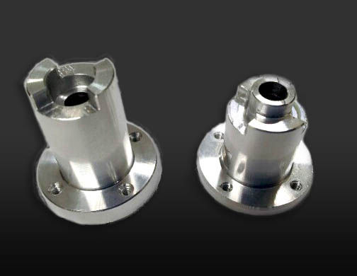
Prototype
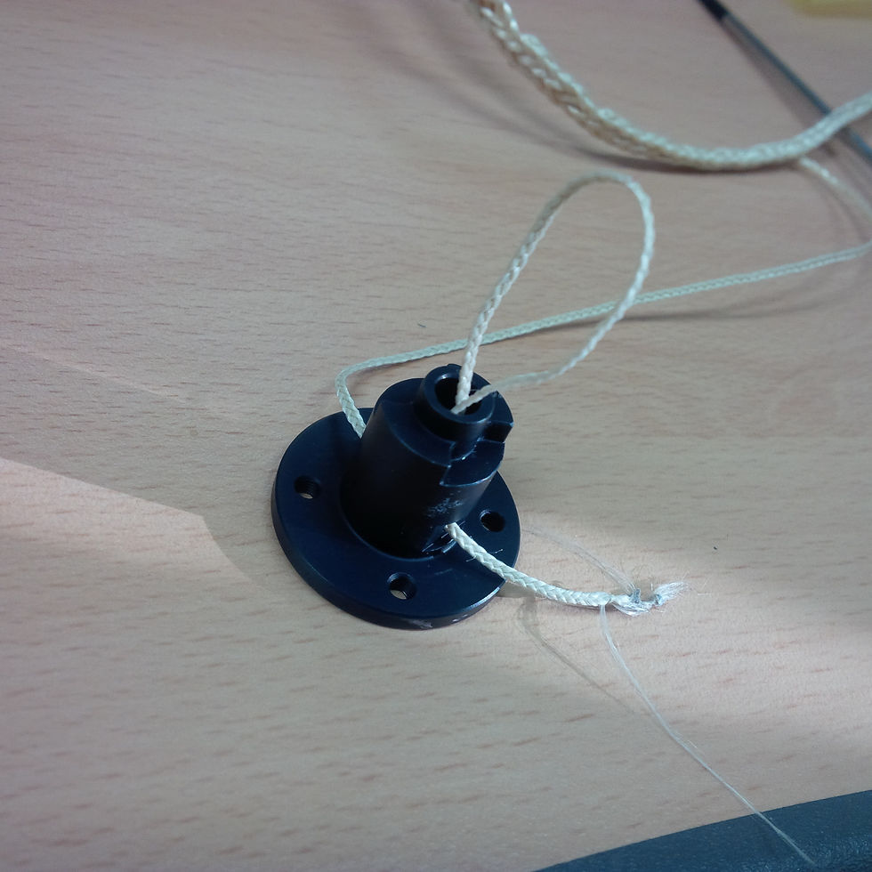
Real Model
Black anodized aluminium 7071 for thermal control issue

Real model
1U and 2U parts are mated together and customized Dyneema rope connects the JERRY and TOM
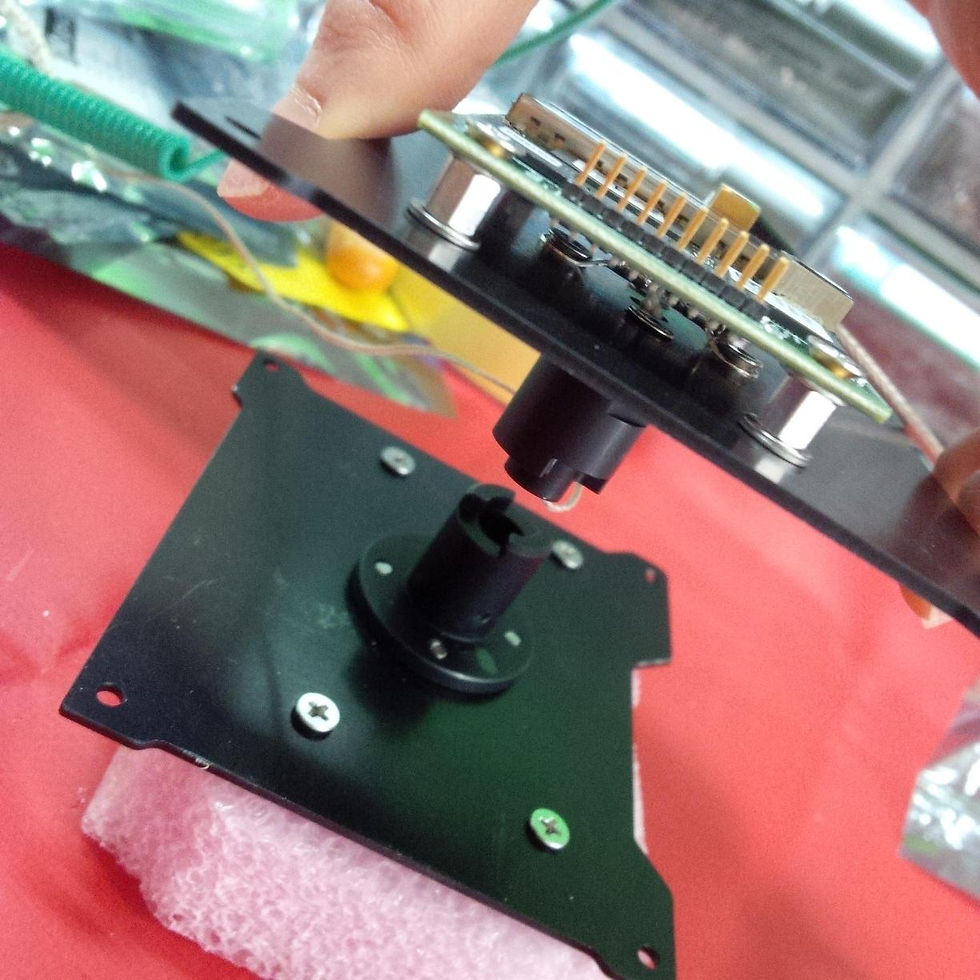
Separation Control Device Module
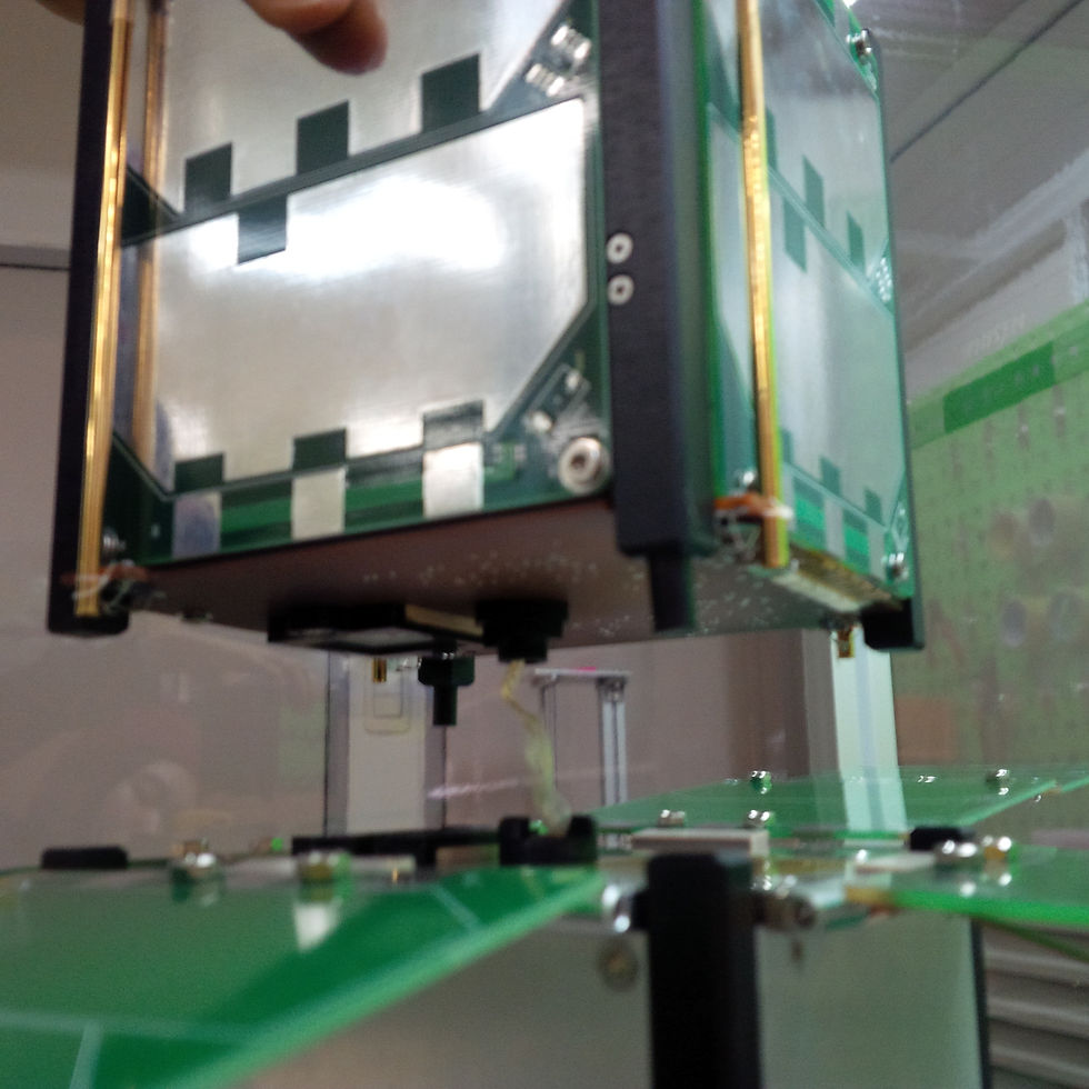
Method of Mating
JERRY is mounted on the top of TOM by mating the Separation Control Device

Thermal Environment Analysis and Test


As part of my responsibility for the thermal control subsystem, I analyzed the thermal state of the Cubesats in different orbits and positions in space using NX I-deas and designed their thermal structures to control the inner and outer temperature of CubeSats. After the simulation, I also evaluated its validity by performing thermal vacuum test with real CubeSat models.
Structural Analysis and Test


Using ANSYS, the 10G acceleration analysis and modal analysis were performed for evaluating the structural characteristics of CubeSats. Also, I performed two structure tests; structure vibration test, and shock test at KAIST
Development of Vision-alignment System Testbed
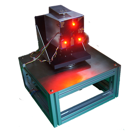

In order to demonstrate the algorithm of the vision sensors that are loaded on Cubesats for enabling the vision-alignment system, I developed a hardware test bed with three degrees of freedom that can be controlled with an accuracy of 0.9˚. As shown in the figure above, it has the same 1-Unit (1U) size of CubeSat and the front panel is detachable. As JERRY (1U) integrates 3 LEDS on its front panel (+x plane), the testbed also has 3 LEDs. By rotating having 3-DOF, it demonstrates JERRY's orientation variation in space environment.
bottom of page